We use cookies, which are small text files, to improve your experience on our website and to show you personalized content. You can allow all or manage them individually.
We believe in making audio personal for you. We’ve pushed boundaries, and we will keep at it. This is us. This is in our DNA, and you can trust us to keep redefining the possibilities of audio.

Why choose Sound Blaster?
You care about stunning graphics, but you’re missing more than half the experience with mediocre audio. Audio is emotive — your heart soars and drops with the beat of audio and cinematic tracks. Ever tried watching a thriller with the audio on mute? We make it our cause to challenge the notion that motherboard audio is enough, because it really isn’t.
You’re missing details that you don’t even know existed. Here are some clips for you to hear the Sound Blaster difference yourself.
-
With Crystallizer
-
Without Crystallizer
-
With Scout Mode
-
Without Scout Mode
This is barely scratching the surface of what Sound Blaster can do for your audio experience. We have 3 decades worth of innovation and technologies that will bring your audio to new heights. Intrigued?

Sound Blaster Products
Redefined into 3 main product series, Sound Blaster provides an audio upgrade solution for every setup for home, work, or play. Find products that answer your audio needs, and you’ll never want to go back to standard PC audio again.
G Series
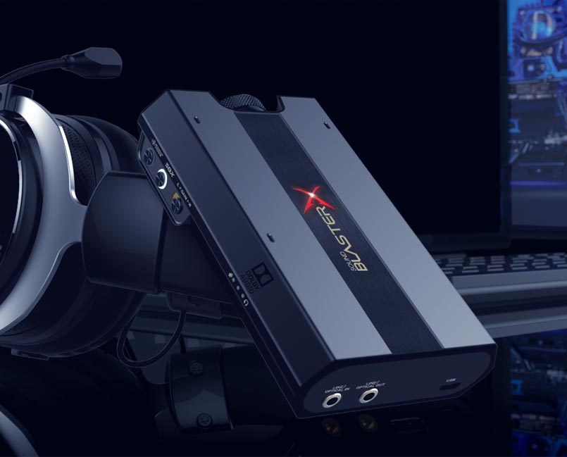
External Portable Gaming USB DAC and Amp
“G” for Gaming — The G-Series of portable and external USB DACs and Amps are must-haves in your quest to up your gaming edge. This series is armed with a myriad of gaming features like GameVoice Mix, Scout Mode, and Advanced 7.1 Virtualization Technology for PlayStation 4, Nintendo Switch, PC, and Mac.
X Series
External Multi-Channel USB DAC and Amp Sound Card
“X” for Movies and Music with Cross-platform Connectivity — Elevate your home entertainment experience with multi-channel surround sound and our critically-acclaimed proprietary Super X-Fi technology in an external USB plug-and-play format that works with PC, Mac, and even gaming consoles like PlayStation 4, and Nintendo Switch.
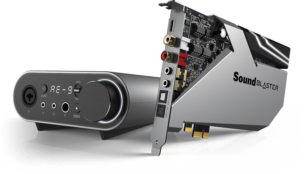
AE Series
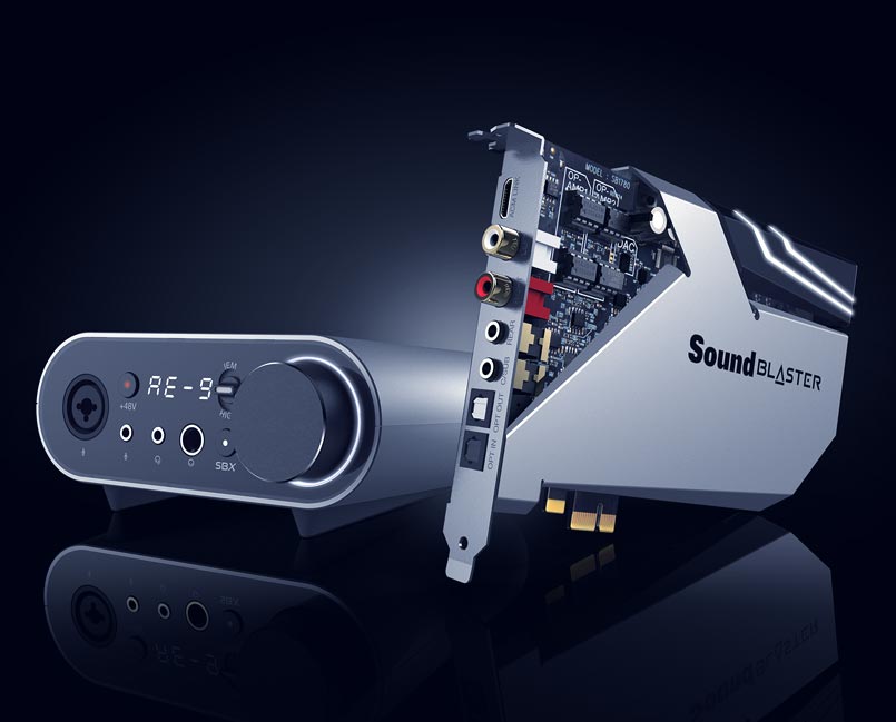
Internal DAC and Amp Sound Card
Hands down — We make the best PCI-e cards available out there in the market with our Acoustic Engine technology. Have the ultimate battle station PC or a custom rig built? The AE series provides you with incredibly high-res audio, Xamp discrete headphone bi-amp with ultra-low 1Ω output impedance, and dedicated audio processing for enhancements that satisfies even the most discerning user. Complete the mission. Get the best video AND audio.

Sound Blaster Software
We’re serious about our software. Redesigned and rewritten from the ground up, the Sound Blaster Command has been overhauled to place more power at your fingertips. Switch between audio profiles, tweak your equalizer, or customize advanced settings like playback resolution, input sources, or even calibrate speakers easily through our powerful and intuitive software.

Join the conversation! We’re actively engaging with fellow Sound Blaster fans and users for feedback and suggestions so we can improve on our existing products or even come up with ideas for new ones!
The Sound Blaster Experience
Still not convinced? Here’s a list of Sound Blaster product reviews from tech reviewers!